Pumps Library
In the pumps section of the equipment library, pump library members can be viewed, modified, or created for use in a TRACE project file.
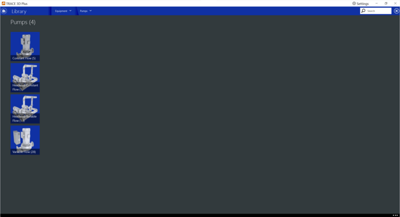
The following pump types are available:


Constant Flow Pumps
In this section you can create new, copy, or modify constant flow pump library members. 
Note: Standard TRACE library members cannot be modified or deleted. 
 
Product tab
 
Full Load Energy
Default: 22 W/gpm, 348701.1 W/(m3/s)
Typical Range: 0 to 999,999,999,999,999
Units: W, hp, kW, therms, W/(m3/sec), W/(gpm), W/(L/sec), W/((m3/sec)·Pa), W/(gpm·ftH2O), W/((L/sec)·Pa)
Enter the Full load energy consumption value and select the appropriate units to describe the amount of energy consumed by this pump.
 
 
Pump Head
Default: 60 ft H2O, 179352 Pa
Typical Range: 0 to 999,999,999,999,999
Units: Pa, kPa, ft H2O
This numeric field contains the pump’s rated head pressure. 
 
 
Motor Efficiency
Default: 90%
Typical Range: 0 to 100
Units: %
This numeric field contains the pump’s efficiency in terms of percent.  For example, if 90% is the desired motor efficiency, enter 90 into the field and not 0.9. 
 
 
Motor Heat to Fluid
Default: 100%
Typical Range: 0 to 100
Units: %
This value is the fraction of the motor heat that is added to the fluid stream. A value of 0 means that the motor is completely outside the fluid stream. A value of 100 means that all of the motor heat loss will go into the fluid stream and act to cause a temperature rise. This value must be between 0 and 100.
 
 
Flow Control
Default: Continuous
You can choose either Continuous or Intermittent. The operation of a constant speed pump is fairly straightforward. If you designate a constant speed pump that is operating continuously, the pump will run regardless of whether or not there is a load. This may have the net effect of adding motor heat to the loop if no equipment besides the pump is turned on. If the pump is constant speed and operates intermittently, the pump will run at its full load capacity if there is a load on the loop and will cycle off if there is no load on the loop. Applicable availability managers (ref. Availability Manager Assignment List*) may override this control by forcing the pump to be on or off.


Variable Flow Pumps Library
 
In this section you can create new, copy, or modify variable flow pump library members. 
Note: Standard TRACE library members cannot be modified or deleted. 


Product tab
  
Full Load Energy
Default: 22 W/gpm, 348701.1 W/(m3/sec)
Typical Range: 0 to 999,999,999,999,999
Units: W, hp, kW, therms, W/(m3/sec), W/(gpm), W/(L/sec), W/((m3/sec)·Pa), W/(gpm·ftH2O), W/((L/sec)·Pa)
Enter the Full load energy consumption value and select the appropriate units to describe the amount of energy consumed by this pump.


Pump Head
Default: 60 ft H2O, 179352 Pa
Typical Range: 0 to 999,999,999,999,999
Units: Pa, kPa, ft H2O
This numeric field contains the pump’s rated head pressure. 


Motor Efficiency
Default: 90%
Typical Range: 0 to 100
Units: %
This numeric field contains the pump’s efficiency in terms of percent. For example, if 90% is the desired motor efficiency, enter 90 into the field and not 0.9. 


Motor Heat to Fluid
Default: 100%
Typical Range: 0 to 100
Units: %
This value is the fraction of the motor heat that is added to the fluid stream. A value of 0 means that the motor is completely outside the fluid stream. A value of 100 means that all of the motor heat loss will go into the fluid stream and act to cause a temperature rise. This value must be between 0 and 100.
 
Minimum Flow
Default: 0% Design Flow
Typical Range: 0 to 999,999,999,999,999
Units: gpm, m3/hr, L/s, m3/s, % Design Flow
This field contains the minimum volumetric flow rate while operating in variable flow capacity rate.
 
Pump Control Type
Default: Continuous
 
You can choose either Continuous or Intermittent. A variable speed pump is defined with maximum and minimum flow rates that are the physical limits of the device. If there is no load on the loop and the pump is operating intermittently, then the pump can cycle off. For any other condition where there is a load on the loop and the pump is operating intermittently or the pump is continuously operating (regardless of the loading condition), the pump will operate and select a flow somewhere between the minimum and maximum limits. In these cases where the pump is running, it will try to meet the flow rate requested by the demand side components. Applicable availability managers (ref. Availability Manager Assignment List*) may override this control by forcing the pump to be on or off.


Curve tab
 
Pump Power Consumed Curve
Select this button to enter part-load unloading curve information for variable volume pumps. This cubic curve represents the pump’s electric consumption at varying water flow rates. Enter the min % of water flow and the maximum percentage of water flow. The minimum percentage of water flow could also be considered the cycle point of the pump.  Once the pump reaches the minimum flow, it will cycle on/off rather than continue unloading along the curve. 
The equation for the Pump Power Consumed Curve is:
 
Where:
y = pumps’s electric consumption (%)
C1 to C4 = coefficients
x = % full waterflow
 
The curve has the following fields:
X Axis: Full Waterflow (%)
Y Axis: Full power (%)
Curve Type: Cubic.
Waterflow Min / Max: Minimum and Maximum Waterflow percentage


Headered Constant Flow Pump Library
 
In this section you can create new, copy, or modify headered constant flow pump library members. A headered pump assembly consists of 2 or more pumps connected together in parallel working in unison to create a single flow rate. 
Note: Standard TRACE library members cannot be modified or deleted. 


Product tab
 
Full Load Energy
Default: 22 W/gpm, 348701.1 W/(m3/sec)
Typical Range: 0 to 999,999,999,999,999
Units: W, hp, kW, therms, W/(m3/sec), W/(gpm), W/(L/sec), W/((m3/sec)·Pa), W/(gpm·ftH2O), W/((L/sec)·Pa)
Enter the Full load energy consumption value and select the appropriate units to describe the amount of energy consumed by this pump.
 
Pump Head
Default: 60 ft H2O, 179352 Pa
Typical Range: 0 to 999,999,999,999,999
Units: Pa, kPa, ft H2O
This numeric field contains the pump’s rated head pressure. 
 
Motor Efficiency
Default: 90%
Typical Range: 0 to 100
Units: %
This numeric field contains the pump’s efficiency in terms of percent. For example, if 90% is the desired motor efficiency, enter 90 into the field and not 0.9. 


Number of Pumps
Default: 2
Typical Range: 2 to 100
The numeric field specifies the number of pumps present in the pump bank. All these pumps are connected in parallel internally.
  
Motor Heat to Fluid
Default: 100%
Typical Range: 0 to 100
Units: %
This value is the fraction of the motor heat that is added to the fluid stream. A value of 0 means that the motor is completely outside the fluid stream.   A value of 100 means that all of the motor heat loss will go into the fluid stream and act to cause a temperature rise. This value must be between 0 and 100.
  
Flow Control
Default: Continuous
 
This is a choice field of Continuous or Intermittent. The operation of a constant speed pump is fairly straightforward. If the user designates a constant speed pump that is operating continuously, the pump will run regardless of whether or not there is a load. This may have the net effect of adding motor heat to the loop if no equipment besides the pump is turned on. If the pump is constant speed and operates intermittently, the pump will run at its full load capacity if there is a load on the loop and will cycle off if there is no load on the loop. Applicable availability managers (ref. Availability Manager Assignment List*) may override this control by forcing the pump to be on or off.


Headered Variable Flow Pump Library
 
In this section you can create new, copy, or modify headered variable flow pump library members. A headered pump assembly consists of 2 or more pumps connected together in parallel working in unison to create a single flow rate. 
Note: Standard TRACE library members cannot be modified or deleted. 


Product tab
 
Full Load Energy
Default: 22 W/gpm, 348701.1 W/(m3/sec)
Typical Range: 0 to 999,999,999,999,999
Units: W, hp, kW, therms, W/(m3/sec), W/(gpm), W/(L/sec), W/((m3/sec)·Pa), W/(gpm·ftH2O), W/((L/sec)·Pa)
Enter the Full load energy consumption value and select the appropriate units to describe the amount of energy consumed by this pump.
 
Pump Head
Default: 60 ft H2O, 179352 Pa
Typical Range: 0 to 999,999,999,999,999
Units: Pa, kPa, ft H2O
This numeric field contains the pump’s rated head pressure. 
 
 
Motor Efficiency
Default: 90%
Typical Range: 0 to 100
Units: %
This numeric field contains the pump’s efficiency in terms of percent. For example, if 90% is the desired motor efficiency, enter 90 into the field and not 0.9. 
 
Number of Pumps
Default: 2
Typical Range: 2 to 100
The numeric field specifies the number of pumps present in the pump bank. All these pumps are connected in parallel internally.
 
Motor Heat to Fluid
Default: 100%
Typical Range: 0 to 100
Units: %
This value is the fraction of the motor heat that is added to the fluid stream. A value of 0 means that the motor is completely outside the fluid stream. A value of 100 means that all of the motor heat loss will go into the fluid stream and act to cause a temperature rise. This value must be between 0 and 100.
 
  
Flow Control Type
Default: Continuous
 
This is a choice field of Continuous or Intermittent. A variable speed pump is defined with maximum and minimum flow rates that are the physical limits of the device. If there is no load on the loop and the pump is operating intermittently, then the pump can cycle off. For any other condition where there is a load on the loop and the pump is operating intermittently or the pump is continuously operating (regardless of the loading condition), the pump will operate and select a flow somewhere between the minimum and maximum limits. In these cases where the pump is running, it will try to meet the flow rate requested by the demand side components. Applicable availability managers (ref. Availability Manager Assignment List*) may override this control by forcing the pump to be on or off.


Curve tab
 
Pump Power Consumed Curve
Select this button to enter part load unloading curve information for variable volume pumps. 
 
This cubic curve represents the pump’s electric consumption at varying water flow rate. Enter the cycle point to tell the program at which flow rate the pump will begin to cycle on/off rather than unload along the curve. The equation for the Pump Power Consumed Curve is:
 
Where:
y = pumps’s electric consumption (%)
C1 to C4 = coefficients
x = % full waterflow
 
The curve has the following fields:
X Axis: Full Waterflow (%)
Y Axis: Full power (%)
Curve Type: Cubic.
Waterflow Min / Max: Minimum and Maximum Waterflow percentage


*See the Reference page for resources used in the help documentation.