Room Drawing Tools
This set of tools are used to create/modify rooms in a building.

Select Rooms
Use Select Rooms to select a room or set of rooms for deletion or marge. When deleted, this tool can be used to create a courtyard space.

With the tool enabled, click on the rooms in the drawing canvas to be deleted or merged.
Alternatively, access the tool using CTRL + SHIFT + S.
Once the selection set has been made, if rooms are eligible for deletion, the Delete Icon will be enabled.

Click the icon or use the DELETE KEY to delete the rooms
Input Considerations:
Only rooms that have a path to exterior may be deleted.
If delete is disabled, ensure there is some path to the outside.
Deleted spaces have the remaining boundaries exposed to sun and wind.
Merge Rooms
With adjacent spaces selected in the drawing canvas, use the Merge Rooms button to merge them together into one space.

Once clicked, the tool requests a basis room be selected.

The basis room provides the information that will be applied to the newly merged room. Room name, Room Type and Plenum Characteristics of the basis room are inherited by the merged room.
Input Considerations:
Standard Rooms and NonStandard Rooms merged together create geometry that may not have walls in some places – examples include T or I shaped rooms merged vertically. The spaces are fully merged and become one space which cannot be split for zoning purposes.
-
Resulting rooms without uniform boundaries through all spanned levels result in Drop Ceiling and Raised Floor removal at time of merge.
-
Adjacent rooms on two levels may be merged together one at a time using the Merge Tool.
-
Move Wall tool can also be used to merge single-level (standard) rooms on a given level.
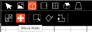
Move Walls
Use the Move Wall tool to move a single wall or to move all wall segments connected to a vertex.

With the tool enabled, all walls and vertices (corners) on the Active Level are rendered in Green.
-
Drag a wall segment to extrude from the endpoints of the room to increase room’s size.
-
To reduce the size of room, drag to shorten the edges.
-
Rooms can be deleted by combining vertices or edges with each other.
-
Create new rooms by extrusion from endpoint of dragged wall.
-
Cancel the tool using ESC or by selecting a different tool.
Input Considerations:
-
Use snapping to ensure alignment with existing geometry.
-
Zoom in or out to reduce or reference more existing geometry during wall moves.
-
To cancel a wall move, use ESC during an active move to cancel the input.
-
Force vertex/vertices’ movement parallel with x-, y- axes using the SHIFT key to keep a vertex (or set of vertices for a wall) in a line parallel to the axes from the original vertex point(s).
-
Use parallel snaps to force a wall parallel to existing geometry.
-
Walls that span more than one level (NonStandard Room Walls) are not currently moved altogether with wall move. Wall movement is bound by the active level. Refer to Level Controls for more information about NonStandard Rooms and Level interactions.
These rules apply to the Peak Line Modification Tool as well.
Draw Rectangle Room
The rectangular room drawing tool is used to quickly create common rectangular rooms.
Open the tool with CTRL + R or click the icon.

Two clicks are needed to create a free-drawn room. Click once to create a corner and once for the opposite corner. Most frequently this will be used when tracing a plan image.
With the dimensions of the room entered, a room is displayed with interior dimensions as entered.
Move the room to the desired location, snapping to existing geometry and click to place the room.
With only length or width has been entered, one edge is displayed with the cursor.
Once the edge has been placed, drag the cursor to extrude the room.
Close the tool with ESC or by selection of another tool.
Length
Use to set the INTERIOR dimension of the room (measured along the X axis for non-rotated room). The length value is retained until changed or cleared, and when navigating out of Create Building.
|
Default: 0 feet or meters (implies free drawn length)
|
|
Typical Range: 10 – 100 feet (3.048 to 30.48 m)
|
|
Min Max: min value: 0 max value: NA
|
|
Units: ft, m
|
Width
Use to set the INTERIOR dimension of the room (measured along the Y axis for non-rotated room). The width value is retained until changed or cleared, and when navigating out of Create Building.
|
Default: 0 feet or meters (implies free drawn length)
|
|
Typical Range: 10 – 100 feet (3.048 to 30.48 m)
|
|
Min Max: min value: 0 max value: NA
|
|
Units: ft, m
|
Angle
Use to set the angle from a line parallel to the X-axis for a rectangle room. This value will be propagated from the Angled Rectangle Tool on subsequent use. This enables creation of rectangle rooms that are not aligned with the axes of the Drawing Grid.
Draw Angled Rectangle Room
Use the Angled Rectangle Tool to create rectangle that is not aligned with axes.

-
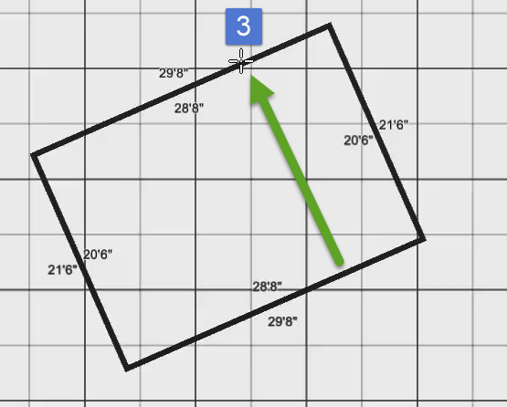
Set the angle by first creating a line that serves as the edge of the room, then drag to extrude the room from the endpoints.
-
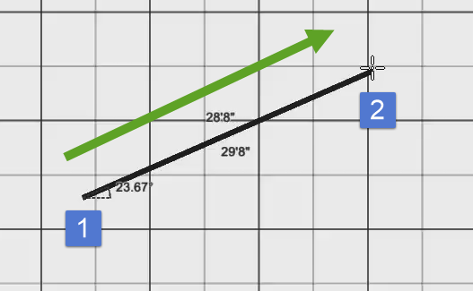
Three clicks are required to create an angled rectangle.
-
The first click creates a starting point for the line segment representing a wall of the room.
-
The second click creates a wall between the two clicks at an angle, typically based on an imported plan image.
-
Drag away from the wall to extrude the rectangle.
-
Use ESC to cancel the tool.
-
Once the angle has been set, it is propagated to the rectangle tool, allowing for standard rectangle tool behavior at the angle inherited from the first two clicks.
Example:
Click to set the endpoint of the first edge. In this example, the wall is 23.67 degrees from the x-axis.

Once entered, the angle field is set based on the drawn input.

Once the cursor is dragged away from the first edge, a rectangle is created.

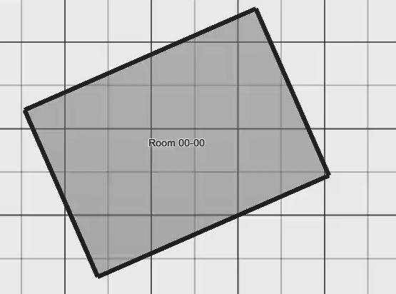
On the third click, the rectangle is placed and is displayed in the tree.

The Rectangle Drawing tool assumes the angle set by this operation, enabling subsequent use of fixed length, width inputs.
Input Considerations:
When setting the angle for the Angled Rectangle tool, use the longest wall in a plan image to achieve the highest precision on the angle. A small error is multiplied with distance away from point of origin.
Draw Polyline Room
Use the polyline tool to create non-rectangular rooms.
Click in the drawing canvas to set the first vertex of a new wall, the second click places the second vertex to complete a wall segment. The tool automatically starts the next wall segment from the location of the second vertex. From that point forward, each (left) click completes a wall segment. This behavior continues until an area has been enclosed (creating a room) or the escape key is pressed (deleting the recently drawn wall segments which did not yet enclose a space).
Use CTRL-Z to remove a wall segment prior to enclosing a space.
Length
The length field can be used to set the length of a wall to an exact value when using the polyline tool. Type the desired wall length into the length field and begin drawing. The length field will remain fixed at the entered value until the length field is cleared.
Input Considerations:
Use the checkboxes for Drop Ceiling and Raised Floor to create rooms with Ceiling and Floor Plenums as they are created. Reference Room and Floor to Floor Height to ensure rooms are created per design deocuments.
When needed, the Edit Wizard can be used to modify a collection of rooms’ Ceiling and Floor Plenums.
Because the polyline tool cannot know until room is submitted which is inside or outside dimension, these values are updated at time of room enclosure.
Any room created assumes the properties of the Default Room Type Template as set in Templates.
Other Room Settings
Room Height
Room height is displayed as a read only value that is calculated as: Room height = Ceiling Elevation – Top of Floor Elevation
Floor to Floor Height
Floor to floor height is displayed as a read-only value that is set in the project defaults screen or the building properties. It is the distance from the top of the floor slab to the top of the inter-zone slab or roof above the room.
Drop Ceiling
The Drop Ceiling checkbox adds an overhead plenum to the rooms to be drawn. The default value is set in the project defaults and may be edited on a room by room basis. The ceiling and underfloor plenum heights are deducted from the floor to floor height to yield the room height.
Raised Floor
The Raised Floor checkbox adds an underfloor plenum to the rooms to be drawn. The default value is set in the project defaults and may be edited on a room by room basis. The ceiling and underfloor plenum heights are deducted from the floor to floor height to yield the room height.
Spans to Top of
Default: Active Level
Range: All levels in the building above the Active Level
Use this input to create rooms that span multiple levels. Most common usages include elevator shafts, stairwells, and tall rooms, such as gymnasiums and lobby spaces.
Room will span from the base elevation to the top of the selected level. Room Height is reflected when input is modified.