Frame and Divider
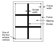
The frame and divider material can be added to both exterior window and glass door constructions. A frame surrounds the glazing in a window as shown in the figure below. It is assumed that all frame characteristics such as width, conductance, and solar absorptance are the same for the top, bottom, and side elements of the frame. If the frame elements are not the same then you should enter area-weighted average values for the frame characteristics.
It is important to note that when a frame and/or divider are added to a window, the area of the glass will be reduced to fit the frame and divider.
EnergyPlus™ adds the frame area around the defined window vertices and automatically subtracts the area of the frame from the area of the wall containing the window.

A divider, also shown in figure above, divides the glazing into separate lites. It is assumed that all divider elements have the same characteristics. If not, area weighted average values should be used. Energy Plus automatically subtracts the divider area from the glazed area of the window.
Frame and divider properties

Frame width
It is the width of the frame elements when projected onto the plane of the window. It is assumed that the top, bottom, and side elements of the frame have the same width. If not, an average frame width should be entered such that the projected frame area, calculated using the average value, equals the sum of the areas of the frame elements.
|
Default value:
|
6 mm; 0.25 in
|
|
Min & Max:
|
0 < x <= 500
|
|
Typical Range:
|
3 to 30 mm; 0.01 to 1.5 in
|
|
Units:
|
mm; in
|
Frame outside projection
It is the amount by which the frame projects outward from the outside surface of the window glazing. If the outer surface of the frame is flush with the glazing, frame outside projection = 0.0. This value is used to calculate shadowing of frame onto the glass, solar absorbed by the frame, IR emitted and absorbed by the frame and convection from the frame.
|
Default value:
|
blank
|
|
Min & Max:
|
0 < x <= 500
|
|
Typical Range:
|
N/A
|
|
Units:
|
mm; in
|
Frame inside projection
It is the amount by which the frame projects inward from the inside surface of the window glazing. If the inner surface of the frame is flush with the glazing, frame projection = 0.0. This value is used to calculate solar absorbed by the frame, IR emitted, and absorbed by the frame and convection from the frame.
|
Default value:
|
blank
|
|
Min & Max:
|
0 < x <= 500
|
|
Typical Range:
|
N/A
|
|
Units:
|
mm; in
|
Frame Conductance
The effective thermal conductance of the frame measured from inside to outside frame surface (no air films) and taking 2-D conduction effects into account. The WINDOW program is a good source for this value.
|
Default value:
|
blank
|
|
Min & Max:
|
0 < x <= 4
|
|
Typical Range:
|
N/A
|
|
Units:
|
W/m2K, W/m2•°C, Btu/h°F
|
Ratio of frame-edge conductance to center of glass
The glass conductance near the frame (excluding air films) divided by the glass conductance at the center of the glazing (excluding air films). This value is used only for multiple glazing constructions. This ratio is greater than 1.0 because of thermal bridging from the glazing across the frame and across the spacer that separates the glass panes. The WINDOW program is a good source for this value.
|
Default value:
|
1
|
|
Min & Max:
|
0 < x <= 4
|
|
Typical Range:
|
N/A
|
|
Units:
|
N/A
|
Frame solar absorptance
This is the solar absorptance of the frame. The value is assumed to be the same on the inside and outside of the frame and to be independent of angle of incidence of solar radiation. If solar reflectance (or reflectivity) data is available, then absorptance is equal to 1.0 minus reflectance (for opaque materials).
|
Default value:
|
0.7
|
|
Min & Max:
|
0 <= x <= 1
|
|
Typical Range:
|
N/A
|
|
Units:
|
N/A
|
Frame visible absorptance
This is the visible absorptance of the frame. The value is assumed to be the same on the inside and outside of the frame and to be independent of angle of incidence of solar radiation. If visible reflectance (or reflectivity) data is available, then the absorptance is equal to 1.0 minus reflectance (for opaque materials).
|
Default value:
|
0.7
|
|
Min & Max:
|
0 <= x <= 1
|
|
Typical Range:
|
N/A
|
|
Units:
|
N/A
|
Thermal emissivity
This is the thermal emissivity of the frame. It is assumed to be the same on the inside and outside.
|
Default value:
|
0.9
|
|
Min & Max:
|
0 < x <= 1
|
|
Typical Range:
|
N/A
|
|
Units:
|
N/A
|
Divider type
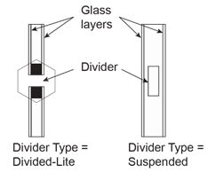
The figure below shows the two types of divider.

Divider Type = Suspended is applicable only to multi-pane glazing. It means that the divider is suspended between the panes. (If there are more than two glass layers, the divider is assumed to be placed between the two outermost layers.)
Divider Type = Divided-Lite means the divider elements project out from the outside and inside surfaces of the glazing and divide the glazing into individual lites. For multi-pane glazing, this type of divider also has between-glass elements that separate the panes.
Divider width
This is the width of the divider elements when projected onto the plane of the window. It is assumed that the horizontal and vertical divider elements have the same width. If not, an average divider width should be entered so that the projected divider area, calculated using the average value, equals the sum of the areas of the divider elements.
|
Default value:
|
6 mm; 0.25 in
|
|
Min & Max:
|
0 <= x <= 1000
|
|
Typical Range:
|
3 to 30 mm; 0.01 to 1.5 in/A
|
|
Units:
|
mm; in
|
Number of horizontal dividers
This is the number of divider elements parallel to the top and bottom of the window.
|
Default value:
|
0
|
|
Min & Max:
|
0 <= x <= 1000
|
|
Typical Range:
|
1-5
|
|
Units:
|
N/A
|
Number of vertical dividers
The number of divider elements parallel to the sides of the window.
|
Default value:
|
0
|
|
Min & Max:
|
0 <= x <= 1000
|
|
Typical Range:
|
1-5
|
|
Units:
|
N/A
|
Divider outside projection
This is the amount by which the divider projects out from the outside surface of the window glazing. For Divider Type = Suspended, the Divider Projection = 0.0. It is used to calculate shadowing of divider onto the glass, solar absorbed by the divider, IR emitted and absorbed by the divider, and convection from the divider.
|
Default value:
|
blank
|
|
Min & Max:
|
0 <= x <= 500
|
|
Typical Range:
|
N/A
|
|
Units:
|
mm; in
|
Divider inside projection
This is the amount by which the divider projects inward from the inside surface of the window glazing. If the inner surface of the divider is flush with the glazing, the Divider inside Projection = 0.0. It is used to calculate solar absorbed by the divider, IR emitted and absorbed by the divider, and convection from the divider.
|
Default value:
|
blank
|
|
Min & Max:
|
0 < x <= 1000
|
|
Typical Range:
|
N/A
|
|
Units:
|
mm; in
|
Divider conductance
The effective thermal conductance of the divider measured from inside to outside divider surface (no air films) and taking 2-D conduction effects into account. The WINDOW program is a good source for this value.
|
Default value:
|
blank
|
|
Min & Max:
|
0 < x <= 100,000
|
|
Typical Range:
|
N/A
|
|
Units:
|
W/m2K, W/m2•°C, Btu/h°F
|
Ratio of divider-edge conductance to center of glass
The glass conductance near the divider (excluding air films) divided by the glass conductance at the center of the glazing (excluding air films). It is used only for multi-pane glazing constructions. This ratio is greater than 1.0 because of thermal bridging from the glazing across the divider and across the spacer that separates the glass panes. The WINDOW program is a good source for this value.
|
Default value:
|
1
|
|
Min & Max:
|
0 < x <= 4
|
|
Typical Range:
|
N/A
|
|
Units:
|
N/A
|
Divider solar absorptance
This is the solar absorptance of the divider. The value is assumed to be the same on the inside and outside of the divider and to be independent of angle of incidence of solar radiation. If solar reflectance (or reflectivity) data is available, then absorptance is equal to 1.0 minus reflectance (for opaque materials).
|
Default value:
|
blank
|
|
Min & Max:
|
0 < x <= 1
|
|
Typical Range:
|
N/A
|
|
Units:
|
N/A
|
Divider visible absorptance
This is the visible absorptance of the divider. The value is assumed to be the same on the inside and outside of the divider and to be independent of angle of incidence of solar radiation. If visible reflectance (or reflectivity) data is available, then absorptance is equal to 1.0 minus reflectance (for opaque materials).
|
Default value:
|
blank
|
|
Min & Max:
|
0 < x <= 1
|
|
Typical Range:
|
N/A
|
|
Units:
|
N/A
|
Divider thermal emissivity
This is the thermal emissivity of the divider, assumed the same on the inside and outside.
|
Default value:
|
blank
|
|
Min & Max:
|
0 < x < 1
|
|
Typical Range:
|
N/A
|
|
Units:
|
N/A
|
Is the window flush with the wall?
The fields below are active if the window has a reveal (is not flush with the wall). From this information and from the geometry of the window and the sun position, the program calculates beam solar radiation absorbed and reflected by the top, bottom, right and left sides of outside and inside window reveal surfaces. In doing this calculation, the shadowing on a reveal surface by other reveal surfaces is determined using the orientation of the reveal surfaces and the sun position.
It is assumed that:
-
The window is an exterior window.
-
The reveal surfaces are perpendicular to the window plane.
-
If an exterior shade, screen or blind is in place it shades exterior and interior reveal surfaces so that in this case there is no beam solar on these surfaces.
-
If an interior shade or blind is in place it shades the interior reveal surfaces so that in this case there is no beam solar on these surfaces.
-
The possible shadowing on inside reveal surfaces by a window divider is ignored.
-
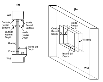
The outside reveal surfaces (top, bottom, left, right) have the same solar absorptance and depth. This depth is not input here but is automatically determined by the program—from window and wall vertices-as the distance between the plane of the outside face of the glazing and plane of the outside face of the parent wall.
-
The inside reveal surfaces are divided into two categories: (1) the bottom reveal surface, called here the "inside sill;" and (2) the other reveal surfaces (left, right and top).
-
The left, right and top inside reveal surfaces have the same depth and solar absorptance. The inside sill is allowed to have depth and solar absorptance values that are different from the corresponding values for the other inside reveal surfaces.
-
The inside sill depth is required to be greater than or equal to the depth of the other inside reveal surfaces. If the inside sill depth is greater than zero the depth of the other inside reveal surfaces is required to be greater than zero.
-
The reflection of beam solar radiation from all reveal surfaces is assumed to be isotropic diffuse; there is no specular component.
-
Half of the beam solar reflected from outside reveal surfaces goes towards the window; the other half goes back to the exterior environment (i.e., reflection of this outward-going component from other outside reveal surfaces is not considered).
-
The half that goes towards the window is added to the other solar radiation incident on the window. Correspondingly, half of the beam solar reflected from inside reveal surfaces goes towards the window, with the other half going into the zone. The portion going towards the window that is not reflected is absorbed in the glazing or is transmitted back out into the exterior environment.
-
The beam solar that is absorbed by outside reveal surfaces is added to the solar absorbed by the outside surface of the window's parent wall; similarly, the beam solar absorbed by the inside reveal surfaces is added to the solar absorbed by the inside surface of the parent wall.
The net effect of beam solar reflected from outside reveal surfaces is to increase the heat gain to the zone, whereas the effect of beam solar reflected from inside reveal surfaces is to decrease the heat gain to the zone since part of this reflected solar is transmitted back out the window. If the window has a frame, the absorption of reflected beam solar by the inside and outside surfaces of the frame is considered. The shadowing of the frame onto interior reveal surfaces is also considered.
The figure below shows a graphic representation of the reveal values.

Outside reveal solar absorptance
This is the solar absorptance of outside reveal surfaces.
|
Default value:
|
blank
|
|
Min & Max:
|
0 < x <= 1
|
|
Typical Range:
|
N/A
|
|
Units:
|
N/A
|
Inside sill depth
This is the depth of the inside sill, measured from the inside surface of the glazing to the edge of the sill.
|
Default value:
|
blank
|
|
Min & Max:
|
0 <= x <= 2000
|
|
Typical Range:
|
N/A
|
|
Units:
|
mm; in
|
Inside sill solar absorptance
This is the solar absorptance of the inside sill.
|
Default value:
|
blank
|
|
Min & Max:
|
0 < x <= 1
|
|
Typical Range:
|
N/A
|
|
Units:
|
N/A
|
Inside reveal depth
This is the depth of the inside reveal surfaces other than the sill, measured from the inside surface of the glazing to the edge of the reveal surface.
|
Default value:
|
blank
|
|
Min & Max:
|
0 <= x <= 2000
|
|
Typical Range:
|
N/A
|
|
Units:
|
mm; in
|
Inside reveal solar absorptance
This is the solar absorptance of the inside reveal surfaces other than the sill.
|
Default value:
|
blank
|
|
Min & Max:
|
0 < x <= 1
|
|
Typical Range:
|
N/A
|
|
Units:
|
N/A
|