Select Plants
Select Plants
The Create Plants screen allows for the addition of plant configurations from the library or the creation of custom plants configurations by combining individual loops
Plant loop types include chilled water, hot water, condenser, VRF, mixed water (or WSHP), and heat exchanger loops. There are no limits on the number of loops to be created within the program.
Plant loops can be linked or connected in order to properly condition a building. In order to make the connections, the loops are broken into supply and demand sides. The demand side will contain equipment that places a load on the supply side equipment. Each supply side of a loop must be connected to a demand side of a loop (and vice versa).
The Select Plants screen includes a plants tree, a button to add plant configurations, buttons to add loops, plant diagram(s), as well as the ability to view properties of the plant created.
Select Plants Tree Features
The Select Plants Tree lists the loops with their respective components and controls beneath them.
The select plants tree has the following levels:
· Building – the name of the building containing the plants.
· Loop name – specified by you or from the library
· Category of components – there are three categories, Components, Controls and Demand Loads.
o Components includes the equipment located in the supply side of the loop.
o Controls includes any water temperature controllers that have been added to the loop.
o Demand Loads will only be shown in the tree when a process or non-process loop load has been added.
In the tree, if there is a component that is not linked to another loop and it is required, there will be a broken link line  signifying that it needs to be assigned to demand equipment. This can be done in the Assign Loops section.
If the equipment is connected to a specific piece of equipment (e.g. a branch pump with a chiller), then that equipment will be listed beneath it and indented.
All names in the tree (this is true for all trees in the plants section) will be tag names associated to the library member assigned.
Plant Wizard
This button will add a plant configuration from the library into the project. Plant configurations are combinations of loops from the Loops Library that have the supply-demand connections of components. These will need to be pre-assigned to each other (for example a chiller assigned to a cooling tower) if you are making a custom plant configuration; the default plant configurations already have the necessary loop assignments.
This button will add a chilled water loop library member. The Chilled Water Loop uses equipment to produce and distribute cold water to cooling coils that have the load requirements from the building. Below is a simple line diagram for a chilled water loop.
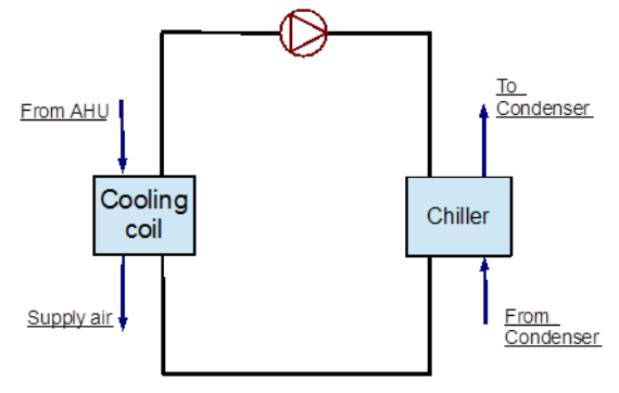
The chilled water loops have a blue loop symbol  next to their name in the tree.
Add Hot Water Loop
This button will add a hot water loop library member. The Hot Water Loop uses equipment to produce and distribute hot water to heating coils that have the load requirements from the building. Below is a simple line diagram for a hot water loop*.

The hot water loops have a red loop symbol  next to their name in the tree.
This button will add a condenser water loop library member. The Condenser Water Loop uses equipment to expel the heat removed from the building to the atmosphere and return cooled water to the chiller in the chilled water loop. Below is a simple line diagram for a condenser water loop*.
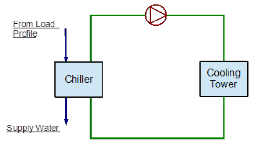
The condenser water loops have a white loop symbol  next to their name in the tree.
This button will add a VRF loop library member. The VRF Loop is a combination of outdoor condensing units and other components that are tied to a group of indoor heating and/or cooling units via a refrigerant loop. Below is a simple line diagram for a VRF loop*.

The VRF loops have a green loop symbol  next to their name in the tree.
This button will add a mixed water loop library member. The Mixed Water loop uses cooling/heating equipment along with heat rejection and heating equipment to maintain a set range of water temperature for a system. Building loads can be met with several modes of operation depending on the outside conditions. The individual space equipment can switch between cooling and heating depending on space needs. The goal of the system is to recover heat or use “free cooling” whenever possible. Below is a simple line diagram for a mixed water loop*.
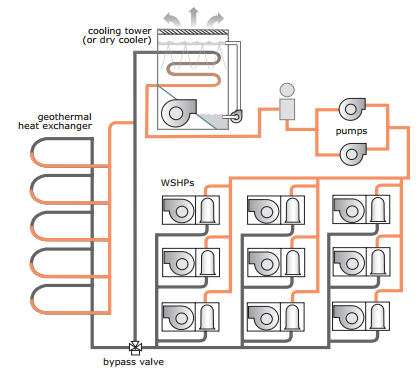
The mixed water loops have a purple loop symbol  next to their name in the tree.
This button will add a heat exchanger loop library member. Once clicked it will open up several different types of available heat exchanger loops for the project.
Heat Exchanger Loops transfer heat from one medium or loop to another for different purposes like energy saving, chilled water or ice storage, etc. Below is a simple diagram example of a heat exchanger loop.
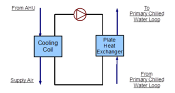
There are eight different types of Heat Exchanger Loops depending on the placement of the heat exchanger and the loop types it connects. Keep in mind, the categories of the heat exchanger loops should be read as “supply to demand.” For example, the “Chilled Water Loop to Chilled Water Heat Exchanger” means a heat exchanger loop with a chiller will supply cold water to the heat exchanger in a chilled water loop.
The heat exchanger loops have an orange loop symbo l next to their name in the tree.
● Chilled Water Loop to Chilled Water HX
A heat exchanger loop with a chiller supplies cold water to the heat exchanger in a chilled water loop.

● Chilled Water Loop to Mixed Water HX
A heat exchanger loop with a chiller supplies cold water to the heat exchanger in a mixed water loop.
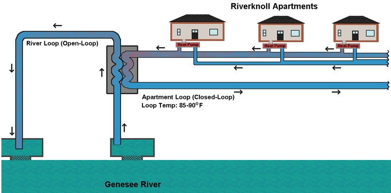
● Hot Water Loop to Mixed HX
A heat exchanger loop with a hot water source supplies water to the heat exchanger in a mixed water loop.
● Hot Water Loop to Hot Water HX
A heat exchanger loop with a hot water source supplies water to the heat exchanger in a hot water loop.
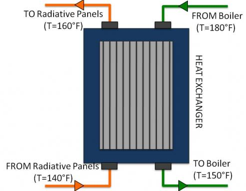
● Condenser Loop to Condenser Water HX
A heat exchanger loop with a condenser supplies water to the heat exchanger in a condenser water loop.
● Condenser Loop to Chilled Water HX - some examples are free cooling applications.
A heat exchanger loop with a condenser supplies water to the heat exchanger in a chilled water loop. An example would be a free cooling application.
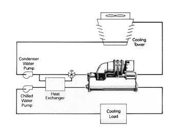
● Condenser Loop to Mixed Water HX
A heat exchanger loop with a condenser supplies water to the heat exchanger in a mixed water loop.
● Mixed Water Loop to Hot Water HX
A heat exchanger loop with heating and/or condenser and/or geothermal equipment supplies water to the heat exchanger in a hot water loop.
● Mixed Water Loop to Chilled Water HX
A heat exchanger loop with heating and/or condenser and/or geothermal equipment supplies water to the heat exchanger in a chilled water loop.